The Portfolio of Kaiser Islam
Civil Engineering Graphics
This page outlines the skills I developed in SketchUP and AutoCAD in relation to Civil Engineering drawings
Summary
There are three main parts to this section: AutoCAD, SketchUP and freehand drawings. AutoCAD was used to create 2D drawings and creating dimensions for given drawings. SketchUP was used for 3D modelling different civil engineering aspects. Lastly, simple freehand techniques were learned to show students how to create rough drafts quickly and accurately
I've developed these skills through creating various models such as steel plates, box girder segments and contour elevations.
Reflections and the Importance of Graphical Communication in the Civil Engineering Industry
These skills were taught in CIV235 in second year at UofT, and was an important introduction to the three skills listed above, since it provided students with the basic knowledge for each skill and provided enough intuition to ensure that future learning is met with few challenges. I am now familiar with most of the basic tools in AutoCAD and Sketchup and can create both 2D and 3D models quickly and efficiently as well as import them into a layout editor (either Paper Space in AutoCAD or LAYOUT with SketchUP). In regards to freehand drawings, though I won't become an artist any time soon, I now know various approaches to take when drawing common civil engineering models, such as box girders; I can also combine different techinques together, should the sketch require.
One aspect of the course which will be particularly useful on site was going over how to read engineering drawings. This wasn't a main focus of the course, but introduced students to the basics of engineering drawings and how to traverse them (i.e. finding specific schedules and sections, using different views to determine dimensions of a model etc.) which is quite useful in the construction aspect of civil engineering. To put together these technical drawings, one can first use freehand sketching to get a general idea of what the model should look like and then use both AutoCAD and SketchUP to transfer ideas from paper to computer. The 2D models can be created with AutoCAD and the 3D model designed via SketchUP. Finally, both paper space and LAYOUT can be applied to put all of the models together and create a complete set of drawings.
AutoCAD
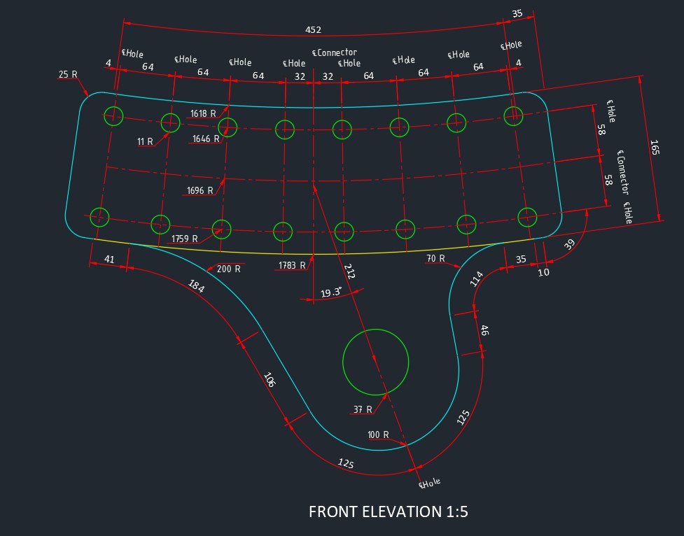 The first part of graphics which I developed an understanding of was 2D drawing in AutoCAD, taking my first step in civil engineering graphics. At the start of the year, I was given a set of engineering drawings with specific dimensions to replicate in AutoCAD (Click here for an image of one of the earlier projcts). This was done using a basic set of 2D drawing tools, polyline and 2D arcs. A .dwg template was created to ensure that layers were used efficiently to highlight key aspects of a drawing. This involved determining which parts of the drawing
were going to be in the foreground and what may be in the background/hidden. The other basic part of AutoCAD was learning how to properly dimension objects. There were two main points which were incorportated here: what type of dimension to use and which part of the model is redundant to dimension. About the first point, I properly dimensioned straight and curved objects to ensure maximum clarity. This can be seen on the left image; with the curved dimensions, some of the curves required one to figure out the actual length and then use angular dimensions instead of aligned
dimensions, since it would convey more clarity. I learned about what parts of the model where dimensions were redundant, such as modelling half of a symmetrical shape to ensure maximum clarity. As the year progressed, the projects became more advanced and I eventually learned to create and dimension contours and (only dimension) more complex shapes, as seen by the final project on the left.
The first part of graphics which I developed an understanding of was 2D drawing in AutoCAD, taking my first step in civil engineering graphics. At the start of the year, I was given a set of engineering drawings with specific dimensions to replicate in AutoCAD (Click here for an image of one of the earlier projcts). This was done using a basic set of 2D drawing tools, polyline and 2D arcs. A .dwg template was created to ensure that layers were used efficiently to highlight key aspects of a drawing. This involved determining which parts of the drawing
were going to be in the foreground and what may be in the background/hidden. The other basic part of AutoCAD was learning how to properly dimension objects. There were two main points which were incorportated here: what type of dimension to use and which part of the model is redundant to dimension. About the first point, I properly dimensioned straight and curved objects to ensure maximum clarity. This can be seen on the left image; with the curved dimensions, some of the curves required one to figure out the actual length and then use angular dimensions instead of aligned
dimensions, since it would convey more clarity. I learned about what parts of the model where dimensions were redundant, such as modelling half of a symmetrical shape to ensure maximum clarity. As the year progressed, the projects became more advanced and I eventually learned to create and dimension contours and (only dimension) more complex shapes, as seen by the final project on the left.
SketchUP
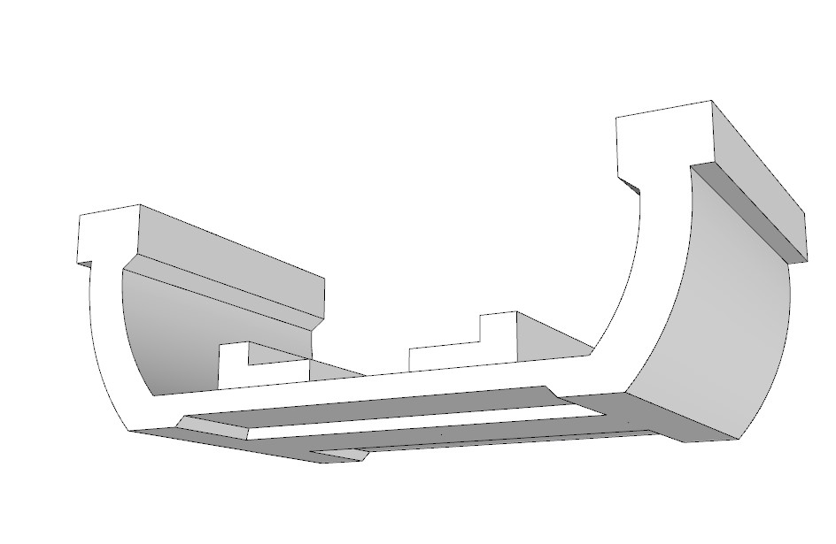 AutoCAD is a good way to create different views of an object for a quick visual, though it is crucial that one can 3D model said object as well. This is where SketchUP plays in; similar to AutoCAD, I looked at a set of drawings for an object to modelm but this time in three dimensions. I started off with the basics by creating simple box girders. This involved setting up gridlines to create proper measurements and adding lines where needed. After creating the models, the most important scenes were created for later use in LayOut.
To do this, I first had to check whether the model was in parallel-projection or perspective view to make sure that it was clearly visible within the scene required. For example, if a plan view was required, we would need a parallel-projection view since it would only show the lines, rather than having part of the model in the background, which is the case with perspective. Once I got a handle on the basics, I began to look at more complex models such as the one on the right and steel plates. After making several
physical 3D models of girders and plates, I also looked at how to create contour elevations and create different views.
AutoCAD is a good way to create different views of an object for a quick visual, though it is crucial that one can 3D model said object as well. This is where SketchUP plays in; similar to AutoCAD, I looked at a set of drawings for an object to modelm but this time in three dimensions. I started off with the basics by creating simple box girders. This involved setting up gridlines to create proper measurements and adding lines where needed. After creating the models, the most important scenes were created for later use in LayOut.
To do this, I first had to check whether the model was in parallel-projection or perspective view to make sure that it was clearly visible within the scene required. For example, if a plan view was required, we would need a parallel-projection view since it would only show the lines, rather than having part of the model in the background, which is the case with perspective. Once I got a handle on the basics, I began to look at more complex models such as the one on the right and steel plates. After making several
physical 3D models of girders and plates, I also looked at how to create contour elevations and create different views.
Freehand Drawings
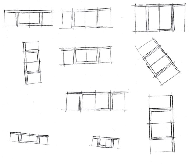 The last main part of this section is freehand drawing. Although the software above can draw these models for us very accurately with proper dimensions, it's good to develop skecthing skills so that one can quickly create rough drafts for large scale projects. Throughout the year, I learned how to swiftly draw fairly authentic shapes, such as ellipses, rectangles, and parabolas. I then extended these basic drawings and combined them to
create more complex shapes, such as cylinders. Once I got the basics down, I began to draw objects which one might find on the construction site, such as the box girder segments seen on the left. This is quite useful as I can then connect these complex shapes together to form a more complete picture of a project.
The last main part of this section is freehand drawing. Although the software above can draw these models for us very accurately with proper dimensions, it's good to develop skecthing skills so that one can quickly create rough drafts for large scale projects. Throughout the year, I learned how to swiftly draw fairly authentic shapes, such as ellipses, rectangles, and parabolas. I then extended these basic drawings and combined them to
create more complex shapes, such as cylinders. Once I got the basics down, I began to draw objects which one might find on the construction site, such as the box girder segments seen on the left. This is quite useful as I can then connect these complex shapes together to form a more complete picture of a project.