The Portfolio of Kaiser Islam
Steel Design
Summary
This section outlines the skills I developed in SAP2000 to create a preliminary design for a four storey office building. Some of these skills include adding members to a SAP2000 model, defining load combinations and using the Handbook of Steel Construction (HSC) (S16-19) to select W sections in accordance to governing loads.
Reflections and the Importance of Structural Analysis Software in the Civil Engineering Industry
I worked on this project with three of my colleagues in CIV312 - Steel and Timber Design, a third year design course at UofT. This course was a great introduction to proper strucutral analysis software in comparison to the drafting softwares, AutoCAD and SketchUP, which I learned last year. This project has shown me the importance of creating preliminary designs using software and how one can save quite a bit of time if they modelled their design and tested it for multiple load combinations digitally rather than with traditional pen and paper. In addition to learning some of the basics of SAP2000, I also learned how to use a design calculator to determine the proper sections to use for each of the differnet parts of the structure; this calculator performs all of the design checks required for the section to pass, depending on its type (column, beam or beam-column). This also saves a lot of time because there are multiple checks for each type of member which would take ages to perform manually. In short, I can now create a simple model in SAP2000, define its properties (material, load combinations etc.) and find suitable sections for the governing load using a design calculator for a given type of section (column, beam or beam-column).
Overview
.jpg)
.png)
Creating the model
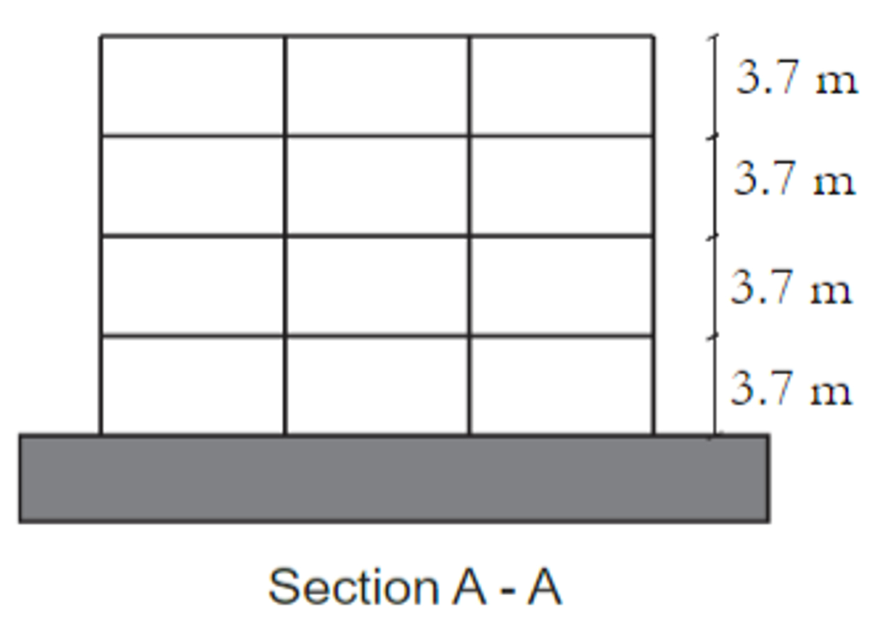
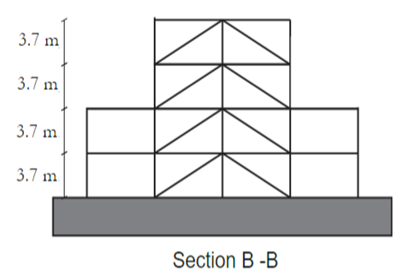
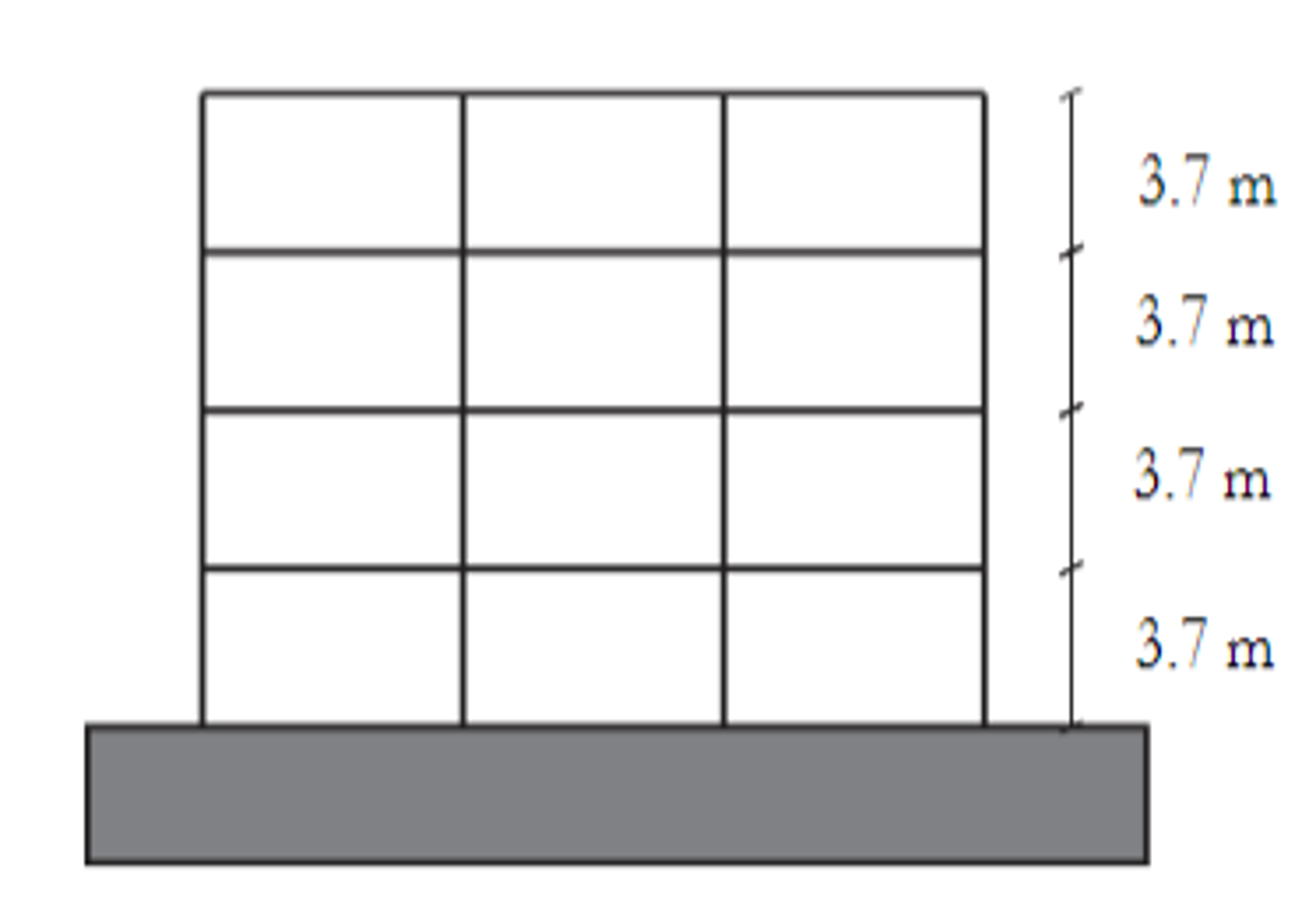
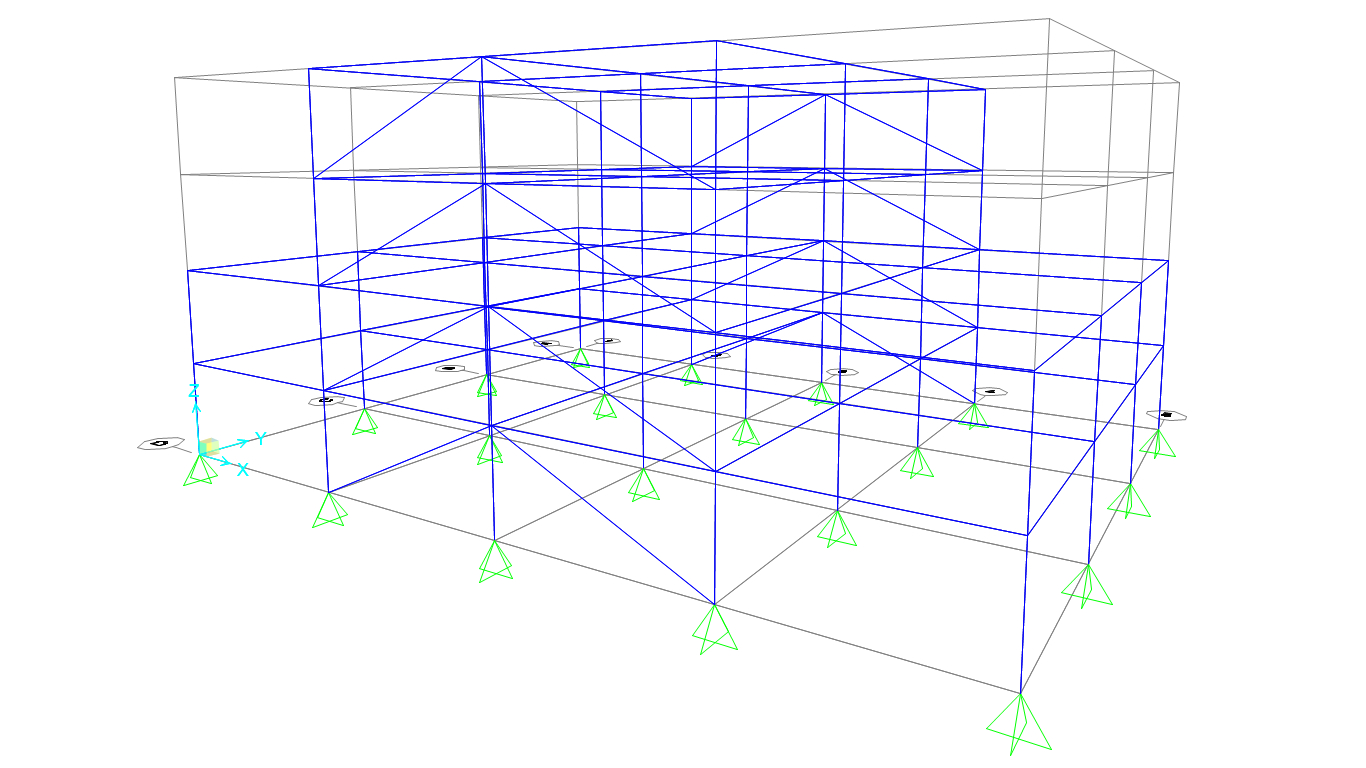
To create the model, we first had to define a grid that matched that of the plan views provided in the overview. Once the grid was defined, we had to define the various loads based on the HSC (S16-19) and National Building Code of Canada (NBCC) (for snow and wind loads). Once all of these loads have been acquired, we inputted them into SAP2000 and defined the load combinations in the NBCC. We then had to apply the loads where they were applicable (ex. applying the two different wind loads: the N-S wind and the E-W wind). We had our model checked over multiple times and when we worked out all of the kinks, we were ready to design the members.
Using a Design Calculator for Member Design
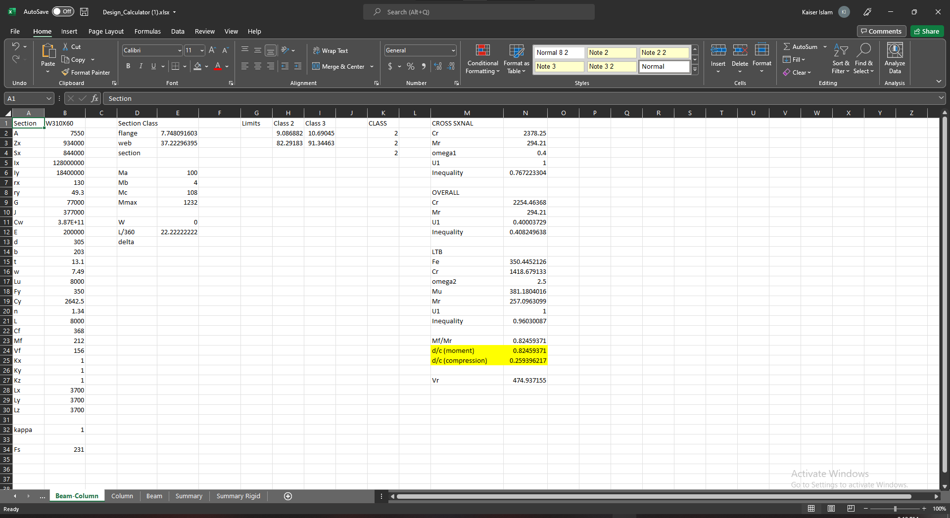 The main part of the project that I worked on was to create preliminary members for each of the frames presented in the "Overview" section; this was made considerably easier with the design calculator on the left. There were multiple calculators depending on what kind of member you were designing and a summary sheet at the end. Firstly, I had to
input the moment or compressive capacity required based on the governing load combination. Next, using the HSC (S16-19), I had to select an initial member using the design tables and input its name and properties into the calculator. This would then allow the calculator to perform all of the checks required and see if the section can handle the applied load.
To determine if the section is adequate, the design-to-capacity (d/c) ratio had to be between 0.85 and 0.99, as this will not only ensure that the member is strong enough, but it is also economical (contains the least mass). Once I found all of the members, I had to define them all in SAP2000 and perform two more iterations because I now had to account for the
self-weight of the sections in the dead load. More than one iteration is required to ensure that the d/c ratio stayed within the range defined. Once all of the members had a d/c ratio within the range defined after accounting for self-weight, I inputted them into SAP2000 as the final sections to use in the design.
The main part of the project that I worked on was to create preliminary members for each of the frames presented in the "Overview" section; this was made considerably easier with the design calculator on the left. There were multiple calculators depending on what kind of member you were designing and a summary sheet at the end. Firstly, I had to
input the moment or compressive capacity required based on the governing load combination. Next, using the HSC (S16-19), I had to select an initial member using the design tables and input its name and properties into the calculator. This would then allow the calculator to perform all of the checks required and see if the section can handle the applied load.
To determine if the section is adequate, the design-to-capacity (d/c) ratio had to be between 0.85 and 0.99, as this will not only ensure that the member is strong enough, but it is also economical (contains the least mass). Once I found all of the members, I had to define them all in SAP2000 and perform two more iterations because I now had to account for the
self-weight of the sections in the dead load. More than one iteration is required to ensure that the d/c ratio stayed within the range defined. Once all of the members had a d/c ratio within the range defined after accounting for self-weight, I inputted them into SAP2000 as the final sections to use in the design.
Designing Connections
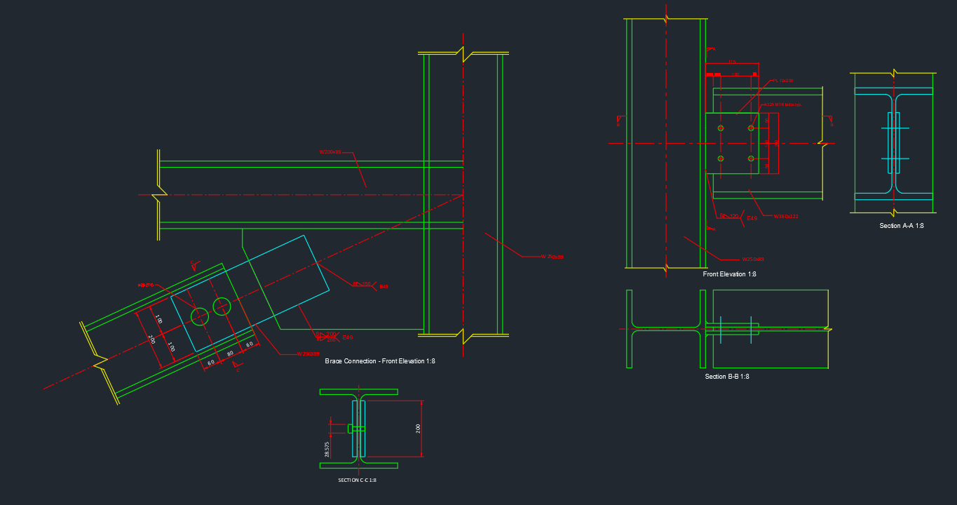 The final part of the project involved detailing the various connections throughout the building. The connections to be designed were beam-column connections, brace connections and base plates. To create these connections, we had to determine the required dimensions by completing checks according to the HSC (S16-19). These design checks included bolt and weld
designs. After the dimensions of the design were determined, we had to model the connections in AutoCAD. To the right is the brace connection which I was in charge of modelling in 2D. This connection involves using both welds and bolts. As you can see, the welds are labelled with flags in accordance to the HSC (S16-19) and the bolts dimensions have been shown,
including their diameters and spacing between each other and the edge.
The final part of the project involved detailing the various connections throughout the building. The connections to be designed were beam-column connections, brace connections and base plates. To create these connections, we had to determine the required dimensions by completing checks according to the HSC (S16-19). These design checks included bolt and weld
designs. After the dimensions of the design were determined, we had to model the connections in AutoCAD. To the right is the brace connection which I was in charge of modelling in 2D. This connection involves using both welds and bolts. As you can see, the welds are labelled with flags in accordance to the HSC (S16-19) and the bolts dimensions have been shown,
including their diameters and spacing between each other and the edge.